Drawing Lines and Shapes
The 2D drawing context has methods for drawing rectangles, lines, curves, arcs, and circles.
Lines, curves, and arcs can be connected at their endpoints to form paths. Paths can be closed to form complex shapes.
Shapes can be stroked (drawn in outline) or filled.
You can set the thickness of lines and strokes.
Strokes and fills can be set to a color, pattern, or gradient.
Set the Stroke and Fill Styles
To actually draw a line or shape, you need to specify a fill style or a stroke style. The stroke or fill style specifies the color the element is drawn in. The following snippet specifies that drawing should be stroked in black or filled in gray at 50% opacity.
ctx.strokeStyle = "black";
ctx.fillStyle = "rgba(128, 128, 128, 0.5)";
The thickness of the stroke is determined by the context’s lineWidth property. The default line width is 1 pixel. To set the line width to 2 pixels, for example, set ctx.lineWidth = 2.
Colors can be specified in any of the usual CSS ways, such as "white", "rgb(255, 255, 255)", or "#ffffff".
Colors can also be specified using RGBa, which specifies the 8-bit RGB values and an alpha value between 0 (transparent) and 1 (completely opaque), such as "rgba(255, 255, 255, 1.0)", for example.
A gradient or pattern can be used instead of a color. For more information, see Gradients and Patterns.
Drawing Rectangles
Once you’ve set a context and a stroke or fill style, you can begin drawing shapes on the canvas. To draw a rectangle, specify the x and y coordinates (with 0,0 in the upper-left corner of the canvas) and the height and width of the rectangle.
There are three rectangle methods:
Use clearRect() to clear a rectangle (erase that area to transparent black).
Use strokeRect() to stroke a rectangle (draw the outline).
Use fillRect() to fill a rectangle in the current color, gradient, or pattern.
The following snippet draws a 50 x 50 blue rectangle at the upper-left corner of the canvas.
function drawBlueRect() { |
ctx.fillStyle = "blue"; |
ctx.fillRect(0, 0, 50, 50); |
} |
Paths and Subpaths
You draw shapes other than rectangles by creating a path, adding elements to it, then calling fill() or stroke().
You begin a path by calling beginPath(). Set the starting point by calling moveTo(x, y). Then add elements such as lines, bezier curves, arcs, and so on. Each element adds a new endpoint to the current path. A path ends when you call beginPath() again. You do not necessarily need to end a path—once you start a path, it becomes the current path, and can be stroked or filled at any time.
A subpath is a continuous part of the path. Initially, the current path and the current subpath are the same. You can use moveTo(x, y) within a path to create a new, discontinuous subpath.
A subpath ends when you call moveTo(x, y) or closePath(). Note that closePath() does not necessarily close the current path, only the current subpath (though they may be the same). The closePath() method draws a line from the current endpoint to the starting point of the current subpath.
Calling fill() or stroke() renders the current path, including all subpaths.
You cannot create multiple paths and fill or stroke them all with a single call to fill() or stroke()—each path you want drawn must be followed by a call to stroke(), fill(), or both, before your next call to beginPath().
Drawing Lines
You draw lines by specifying the endpoint of a line segment. Add an endpoint by using the lineTo() method. The line is drawn from the current endpoint on the path to the new endpoint. You can string endpoints together in a connect-the-dots fashion. Alternatively, set a new starting point for a line segment, without drawing a line to it, by using the moveTo() method.
The lines are not actually drawn until you call the stroke() or fill() method.
If you call the fill() method, the line segments are treated as the outline of a shape, which is filled in the current fill style.
You can adjust the line thickness by setting the context’s lineWidth property. For example, the following snippet sets the line width to 3 pixels.
ctx.lineWidth = 3;
The following snippet draws a horizontal and a vertical line the height and width of the canvas, crossing in the middle of the canvas.
function init() { |
can = document.getElementsByTagName("canvas")[0]; |
ctx = can.getContext("2d"); |
} |
function drawLines() { |
ctx.strokeStyle = "black"; |
ctx.beginPath(); |
ctx.moveTo(0, can.height / 2); |
ctx.lineTo(can.width, can.height / 2); |
ctx.moveTo(can.width / 2, 0); |
ctx.lineTo(can.width / 2, can.height); |
ctx.stroke(); |
} |
Setting Caps and Joins
You can choose how lines are capped at the ends and how they are joined where they meet.
Set the end cap by setting the context’s lineCap property to one of the three values in the following list.
"butt"—Default. Line ends with no cap."round"—Line ends with a round cap."square"—Line ends with a square cap half a line-width long.
Example: ctx.lineCap = "round";
Set the join style by setting the context’s lineJoin property to one of the three values in the following list.
"bevel"—Default. Lines join with a beveled corner."round"—Lines join with a rounded corner."miter"—Lines join with a smoothly mitered corner.
Example: ctx.lineJoin = "round"
The cap and join styles are illustrated in Figure 2-1.
Drawing Bezier Curves
You draw bezier curves in the same connect-the-dots manner as you draw lines, but instead of using the lineTo() method, you use either the bezierCurveTo() method, which connects the endpoints with a cubic bezier curve using a specified pair of control points, or the quadraticCurveTo() method, which connects the endpoints with a quadratic bezier curve using a single specified control point.
The following snippet draws two bezier curves, one cubic and one quadratic, from the upper left corner of the canvas to the lower right corner of the canvas.
function init() { |
can = document.getElementById("can"); |
ctx = can.getContext("2d"); |
var wide = can.width; |
var high = can.height; |
} |
function drawCurves() { |
ctx.strokeStyle = "black"; |
var ctrlX = 5; |
var ctrlY = 150; |
var ctrlXa = 50; |
var ctrlYa = 300; |
ctx.beginPath(); |
ctx.moveTo(0, 0); |
ctx.quadraticCurveTo(ctrlX, ctrlY, wide, high); |
ctx.stroke(); |
ctx.beginPath(); |
ctx.moveTo(0, 0); |
ctx.bezierCurveTo(ctrlX, ctrlY, ctrlXa, ctrlYa, wide, high); |
ctx.stroke(); |
} |
Drawing Arcs and Circles
An arc is a section of a circle. To draw a circle, draw an arc with a starting angle of 0 and ending angle of 2 x Pi.
Draw a freestanding arc by calling arc(x,y,radius,startAngle,endAngle). The x and y parameters specify the center point of the circle the arc is a section of. The radius parameter is the radius of the circle the arc is part of. The startAngle and endAngle parameters are in radians, clockwise, with 0 corresponding to the 3:00 o’clock position on the right of the circle.
Add an arc to the current endpoint of the path by calling arcTo(x, y, radius). The arcTo() method connects the current endpoint with the specified endpoint using an arc. The height of the arc is determined by the radius—the larger the radius, the shallower the arc.
The following snippet draws a circle of radius 50 at the center of the canvas.
function init() { |
can = document.getElementById("can"); |
ctx = can.getContext("2d"); |
} |
function drawCircle() { |
ctx.strokeStyle = "black"; |
ctx.arc(can.width / 2, can.height / 2, 50, 0, Math.PI * 2); |
ctx.stroke(); |
} |
Drawing Complex Shapes
To quickly review—you draw shapes other than rectangles by creating a path, adding line segments, curves, or arcs, and optionally closing the path. You can either stroke or fill a path. A path can contain discontinuous subpaths—lines or shapes that aren’t connected. When filling a path, each of these subpaths is filled independently. If you create a path but don’t close it, the stroke() method draws only the specified path segments, but the fill() method fills a solid shape as if you had closed the path.
You can create complex shapes that contain non-filled areas. For example, you can draw a doughnut by drawing an outer circle clockwise and an inner circle counterclockwise. The area between the circles is filled, but the area inside the smaller circle is left unfilled.
For complex shapes, where a point is surrounded by more than one set of path edges, the non-zero winding number rule is used to determine if a point is within the path and should be filled. If a path overlaps itself going in different directions, some areas may not be filled, even though you might expect them to be inside the shape. For instance, if a path winds around a region once going clockwise and once going counterclockwise, the region is not filled.
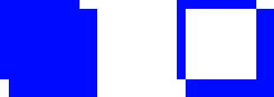
As another example, consider a path consisting of two overlapping, discontinuous polygons. If both polygons are composed entirely of line segments going clockwise, or all going counterclockwise, both rectangles are filled completely. If the two polygons are composed of line segments going in opposite directions, the area where the polygons overlap is not filled.
The example snippet in Listing 2-1 draws two filled paths. Each path consists of a pair of overlapping squares. In one path, the squares are both drawn counterclockwise; in the other path, one square is drawn clockwise and the other counterclockwise. The result is illustrated in Figure 2-2.

Listing 2-1 Exercising the winding rule
function drawPath() { |
// two counterclockwise squares |
ctx.beginPath(); |
ctx.moveTo(10, 10); |
ctx.lineTo(10, 100); |
ctx.lineTo(100, 100); |
ctx.lineTo(100, 10); |
ctx.lineTo(10, 10); |
ctx.moveTo(20, 20); |
ctx.lineTo(20, 120); |
ctx.lineTo(120, 120); |
ctx.lineTo(120, 20); |
ctx.lineTo(20, 20); |
ctx.fill(); |
// two squares, one clockwise, one counterclockwise |
ctx.beginPath(); |
ctx.moveTo(210, 10); |
ctx.lineTo(210, 100); |
ctx.lineTo(300, 100); |
ctx.lineTo(300, 10); |
ctx.lineTo(210, 10); |
ctx.moveTo(320, 20); |
ctx.lineTo(320, 120); |
ctx.lineTo(220 120); |
ctx.lineTo(220, 20); |
ctx.lineTo(320, 20); |
ctx.fill(); |
} |
Creating Masks
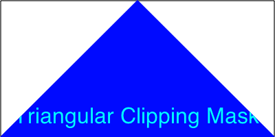
You can make any shape into a mask by calling the context’s clip() method after you define the path. Calling clip() makes the current path the clipping region for the canvas. Any shapes, lines, or images drawn subsequently are clipped if they fall outside the borders of the path.
The example in Listing 2-2 creates a triangle shape, then calls clip() to make the shape a clipping mask. The example then fills the canvas with a blue rectangle and draws some text. The rectangle and text are clipped when they fall outside the boundaries of the triangle, as shown in Figure 2-3. Note that the black outline around the canvas is drawn prior to the mask, and so is unaffected.

Listing 2-2 Making a mask
<html> |
<head> |
<title>Triangular Mask</title> |
<script type="text/javascript"> |
var can, ctx; |
function init() { |
can = document.getElementById("can"); |
ctx = can.getContext("2d"); |
ctx.strokeStyle = "black"; |
ctx.strokeRect(1, 1, can.width - 2, can.height - 2); |
drawMask(); |
} |
function drawMask() { |
// make a triangle with top at mid canvas |
ctx.beginPath(); |
ctx.moveTo(can.width / 2, 0); |
ctx.lineTo(can.width, can.height); |
ctx.lineTo(0, can.height); |
ctx.closePath(); |
// make the current path the clipping region |
ctx.clip(); |
// rectangle and text are clipped to the triangle |
ctx.fillStyle = "blue"; |
ctx.fillRect(0, 0, can.width, can.height); |
ctx.fillStyle = "white"; |
ctx.font = "24pt Helvetica"; |
ctx.fillText("Triangular Clipping Mask", 20, 180); |
} |
</script> |
</head> |
<body onload="init() > |
<h2>Clipping To A Path</h2> |
<canvas id="can" height="200" width="400"> |
</canvas> |
</body> |
</html> |
Copyright © 2013 Apple Inc. All Rights Reserved. Terms of Use | Privacy Policy | Updated: 2013-09-18